Side Quest: Mini Golf Celebration Light Show with a Raspberry Pi 3b and Pico
Building a Mini Golf Hole Light Show (Raspberry Pi + Pico + WS2812B)
This project was a small, self-contained system designed to detect when a golf ball entered a hole and trigger a preprogrammed LED sequence. The final build used a Raspberry Pi 3B for sensing and control, and a Raspberry Pi Pico for LED driving. This was a fun test of using a SBC to control a microcontroller.
The system is split cleanly into two parts:
Raspberry Pi: reads ultrasonic sensor, determines event, sends command
Pico: listens for commands and renders LED effects
The code used in the final build is here:
Full Project: https://github.com/spjca/miniGolfSinkShow
Pi control + sensor logic: https://github.com/spjca/miniGolfSinkShow/blob/main/testing/ultrasonicTestV12.py
Pico LED controller: https://github.com/spjca/miniGolfSinkShow/blob/main/main.py
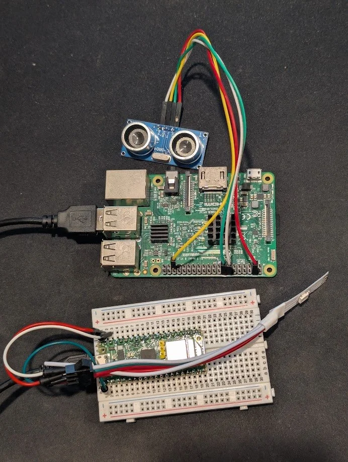
All of the equipment used
Equipment Used
Raspberry Pi 3B
Raspberry Pi Pico
HC-SR04 ultrasonic sensor
WS2812B LED strip (~100 LEDs)
USB cable (Pi ↔ Pico)
External 5V power (recommended for LEDs)
System Layout
The system runs as a loop:
Pi continuously samples distance from ultrasonic sensor
If distance < threshold for consecutive reads → event
Pi sends "celebrate" over serial
Pico switches from idle → animation
After duration, Pico returns to idle
The Pi never directly controls LEDs. It only sends state.
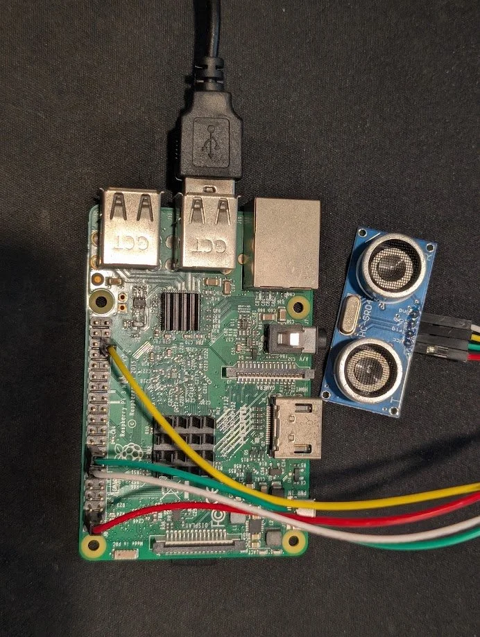
Wiring
1. Ultrasonic Sensor → Raspberry Pi
Pins on HC-SR04:
VCC → Pi 5V
GND → Pi GND
TRIG → GPIO 23
ECHO → GPIO 19 (with voltage divider)
From the code:
TRIG, ECHO = 23, 19Critical detail: ECHO voltage
HC-SR04 outputs 5V on ECHO
Pi GPIO is 3.3V max
You must use a voltage divider:
ECHO → 1kΩ → Pi GPIO
Pi GPIO → 2kΩ → GND
Without this, you risk damaging the Pi. I rolled the dice and was fine so, do what you will with that.
Behavior
Pi sends a 10µs pulse on TRIG
Measures duration of ECHO high signal
Converts to distance
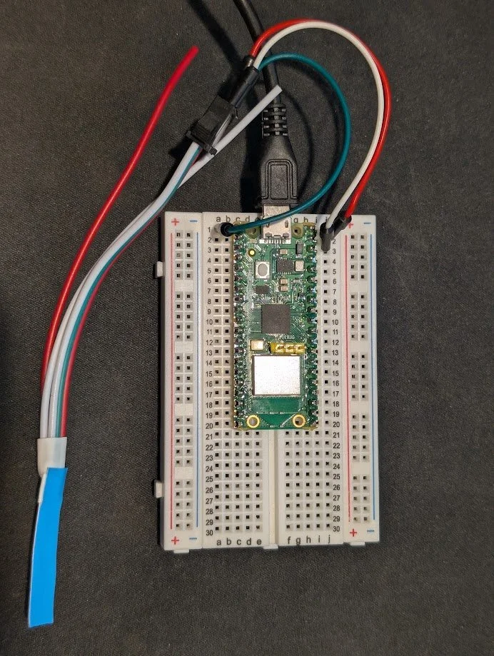
Raspberry Pi Pico wired up to LED strip for testing
2. Raspberry Pi → Pico (USB Serial)
Connection:
Standard USB cable
Pico appears as /dev/ttyACM0
From the code:
PICO_SERIAL_PORT = '/dev/ttyACM0'
PICO_BAUDRATE = 115200
No GPIO wiring between devices.
Communication model
Pi sends newline-terminated strings:
"idle"
"celebrate"
"off"
Example:
pico.write(f"{message.strip()}\n".encode())
Pico reads from stdin and switches modes accordingly.
3. Pico → WS2812B LED Strip
Connections:
LED VCC → 5V power
LED GND → Pico GND
LED DIN → Pico GPIO 0
From the Pico code:
PIN_NUM = 0
np = neopixel.NeoPixel(machine.Pin(PIN_NUM), NUM_LEDS)
Required electrical details
Shared ground
Pico GND must connect to LED GND
If using external power, grounds must be tied together
Power
100 LEDs at full brightness can draw significant current
In practice, brightness is reduced:
BRIGHTNESS = 0.6For longer strips or higher brightness, external 5V supply is required.
Optional stability components
Not required in this build, but standard practice:
330Ω resistor on data line
1000µF capacitor across VCC/GND
Detection Logic (Pi)
Core behavior:
Distance threshold: 5 cm
Require 2 consecutive hits
5 second cooldown
DETECT_CM = 5
CONSEC_HITS_N = 2
COOLDOWN_SEC = 5
This avoids:
false triggers from noise
repeated triggers from same ball
Loop behavior:
sample every ~50ms
increment hit streak if under threshold
trigger only if streak condition met
LED Control Logic (Pico)
The Pico runs a simple state machine:
Idle Mode
shimmer_green()
random green values per LED
updated every 100ms
creates undulating effect
Celebration Mode
Triggered by "celebrate" command:
celebrate(duration=8)
Sequence:
Yellow wave across strip
Random white flashes ("paparazzi")
Loop until duration ends
Return to idle
Command Handling
if line == "celebrate":
    current_mode = "celebrate"
    celebrate()
    current_mode = "idle"
All behavior is driven by simple string commands.
Physical Placement
Ultrasonic sensor mounted ~4.5 inches above hole
Pointed straight down
LED strip runs along lane edge
Key constraint:
Distance threshold depends on mounting height
Must be calibrated relative to empty hole vs ball presence
End State
The final system consists of:
one sensor input
one decision loop
one serial interface
one LED controller
No shared state, no complex synchronization, no custom protocol.
The separation between sensing (Pi) and rendering (Pico) allows each part to remain simple and independently adjustable.
Demo
Video: https://youtube.com/shorts/z6JGqtzPrrA?si=_scmMZ1VB6ez1eMX
The video shows the full loop:
idle shimmer
ball enters hole
celebration sequence
return to idle
This reflects the exact behavior implemented in the final code.
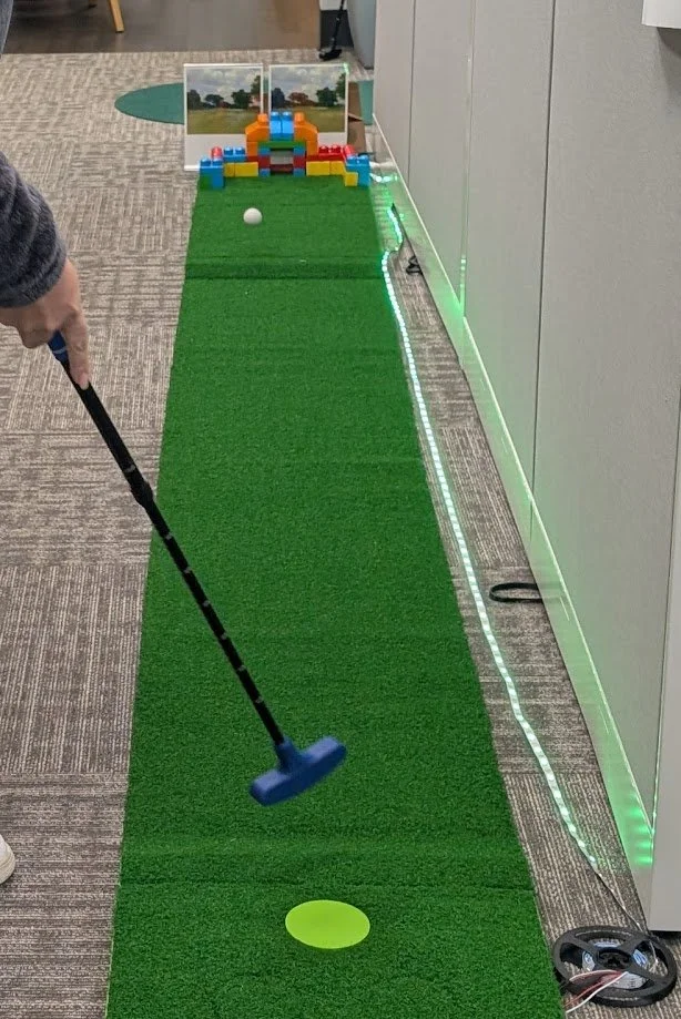
Playing a round of mini golf with the sensors and light show setup